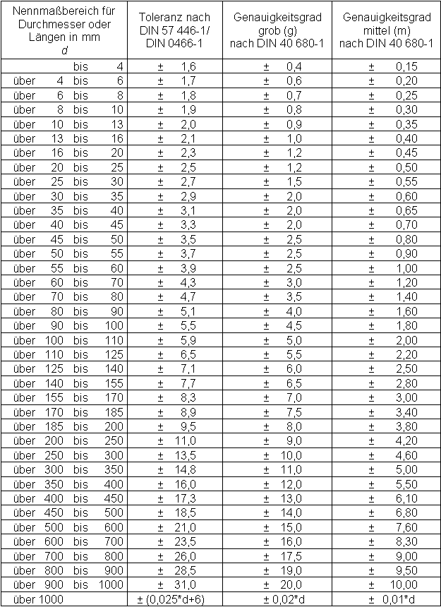
Iso 2768 Hole Tolerance Table
I have some drawings from Germany that use the DIN 2768 tolerances and I am having trouble understanding it correctly. I do not have a full copy of the DIN but I do have some notes and a brief discription of how the tolerances are supposed to work but I still dont quite understand it. The parts are shafts and couplings and have to fit bearings so I know some of the tolerances are going to be plus and some are minus. Could anyone offer a simpler explaination of what I am seeing. One of the external shafts has a f9 while most of the other shafts have a h9 or h6. A keyway has a N9 and the internal keyway has a j59.
Iso 2768 Fh General Tolerance
One of the internal bores has a M6. Most of the tolerances use lower case but some are upper case, I dont know if that makes a difference or not.

Atif aslam songs free download pagalworld. Anyone know of a source for a simpler explaination of these that is in english? Machtool, Yes I got that too, but there are a lot of other tolerances that are not listed in my handbook. I just need to find a better source and I am hoping to not have to buy all the standards if I dont have too. I am just quoting the job and I am still waiting on some answers from the company I got the drawings from. I thought I could get a head start and educate myself at the same time.
One shaft has a dim 25mm f9, a bore is marked M6 and to me that seems super tight, more than the part requires but I am hoping I just read the chart wrong. There are keyways and snap ring grooves and I just cant seem to find all the information I was hoping for in the MHB but I will keep searching. Charles, you have some weird tolerances on there, those are very rare for bearing fits. I have an ISO Tolerance book my company published, but it looks like it is not available any longer. 12mm h9 +0 / -43 25mm f9 -20 / -72 10mm h6 +0 / -9 Is the M6 hole tolerance also 25mm? If so, it would be -4 / -17 By the way, DIN 2768mk is a general tolerance table that provides the tolerances for anything that is not toleranced on the drawing, it does not refer to the diameter tolerances you are asking about.
The ISO System of Limits and Fits is a coordinated system of hole and shaft tolerances for. ISO SYMBOL Hole. TABLE 6-3 PREFERRED HOLE BASIS. Found using tables of limits and fits. Fig 7: Tolerance Grades Selected ISO Fits: The majority of fits required for normal engineering can be provided by a small selection of tolerances and the following hole and shaft tolerances have been found to be. Commonly applied. Selected hole tolerances: H7, H8, H9, H11 Selected shaft.


